For those of you who are regular readers of the blog or indeed my YouTube Channel, you will know I talk an awful lot about the control room.
The control room is the hub of your hot tub and if you get this portion wrong, then you are going to be in trouble. Worst case, your hot tub just won’t work.
For me, as I have said a thousand times, I really wasn’t sure what I was doing when I built my hot tub quite a few years back. Since then, I have gone on to help over 450 people with their own Hot Tub projects.
There was always something in the back of my mind niggling away. The part of the hot tub I was least proud of. That was of course the control room.
Time for a renovation
I made lots of mistakes when I built my own hot tub and most of them are documented here on this blog and on my YouTube channel.
Making the mistakes and learning how to avoid and overcome them means I am well and truly qualified to help others with their projects. Making mistakes is natural. On this site, I help you avoid all the mistakes I made.
Over time, I have been switching out parts, renovating the plumbing on my own tub. Rectifying the original mistakes that I made!
When I sprung a leak in the control room a week or so ago, it seemed the perfect time to do a “control room renovation”. It was just the push I needed. I knew it was going to be a few week’s work for sure.
What was I going to change?
For me, the control room was the part of the hot tub I was least proud of. The pipe work was done badly. The joints were just “made to fit” rather than actually being planned in a logical way. They were forced into position and forced to fit – not how it should be done.
The filter was on its side as it was too tall to fit in the control room from a bad calculation I made. This made changing the cartridge a job that I absolutely hated doing as it was way more involved than it should be. I had to physically remove the filter housing from the plumbing setup each time. Not good!
As I couldn’t completely redo everything as much of the pipework is set into concrete in the tub and I was not about to pull that apart as it works great what was I going to change?
Well, firstly, I was going to cut back the pipework so there was just a connection to the inward plumbing on the skimmer and the bottom drains. Likewise, I planned to remodel the air pipework from the blower and also the outward pipework from the pump.
The size of the control room was always a bit of an issue – it was too small. I planned to add an extra 6” in width so I had some more room to play with.
I also planned to change out the filter for a top loading one to make changing the cartridge a little easier and less of a “project” each month.
Most of all, I wanted to renovate it in a way that I would actually be proud of it. The joints needed to be done well. The pipework needed to be at the correct angles and the darn filter needed to fit vertically, not on an angle!
I must have been in a rush to complete it originally (well, I know I was) as the electrical wiring seemed to be all over the place too.
Yes it has worked for all these years, but it was far from perfect.
There was plenty to do for sure.
Crazy Idea – Let’s Add an Air Source Heat Pump!
Some of you may have already read the article that I wrote on how I fitted an Air Source Heat Pump to my friend Paul’s Hot Tub. This got me thinking. The numbers that he was sending me the first evening after we installed it in terms of heat up speed versus current draw were pretty compelling. Especially when he sent me the screen grabs from his Smart meter.
I know that if I add an Air Source Heat Pump to my own hot tub, the heat up times will dramatically increase from the 0.5C an hour they currently run at. It is really slow. I also think that the running cost of the tub will drop dramatically.
It has been out of service whilst I start the repairs now for a couple of weeks, but I do plan to put it back on and see just how much electric is will consume in a regular week. Especially now that the prices have gone up. Before the price increase, it was costing around £50 ($63) a week to heat. Pretty expensive I know.
I am sure I will be creating separate videos and posts on the air source heat pump side of things so I am not going to go into too much detail here. However, it is going to be an exciting project!
Let’s get started!
The first thing that I needed to do was to drain the tub. As I was going to be cutting out the plumbing, I needed to be well below the control room height so it was not going to flood.
I set the submersible pump running and whilst that was happening, I slowly and carefully remove the blower, pump, pack and filter from the control room. I would be putting most of the original components back in.
With the water drained, it was time to chop out some plumbing. It was not until I removed some of the “interesting” joints that I had made could I see just how bad of a job I had made.
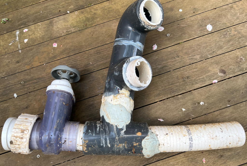
The amount of epoxy putty on the malformed joints was a clear indication.
What I can say with confidence is that my plumbing skills have hugely improved over the last few years with the work that I have been doing for others.
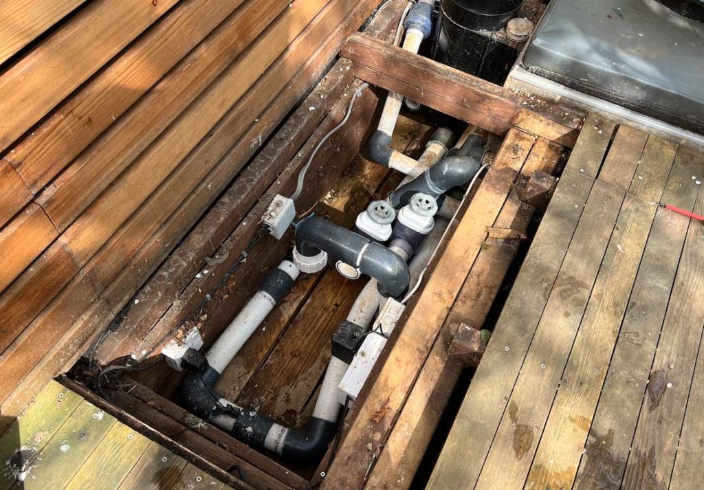
This is the old control room with the pump and the spa pack removed so you can clearly see the state of the plumbing.
Rigid Pipe
The other thing that I wanted to make sure that I was using on this occasion was rigid pipe. rigid pipe is not forgiving in any way. It does not allow you to move a few inches if you have not lined up the joints correctly or squeeze it into place.
The result of me using the rigid pipe was going to be exact joints that were perfectly aligned. If they were not, they would have to be cut out and redone. There was no way I was going to “botch” together any of the joins in this new control room
How a joint should not look.
I don’t mind sharing with you how bad things actually were. This is the section of the inward plumbing where the two lower drains connect to the skimmer and then the front suction on the pump.
Take a look at the joint below and how it was put together. Look at the amount of epoxy putty that is holding it together. Yuk! This is certainly not how joints should look. Why is there putty there in the first place? Easy! The joint was not made properly so it leaked. Go figure! I couldn’t pull it all apart with a tub full of water so I had to patch it up.
TOP TIP – Make your joints properly. Take your time and they will not leak!
Time to dig a bit deeper
With most of the old pipes out of the way, what I was going to do was move the heater to the other side and move the pump over a little more. This was going to give me some more space.
At the back of the control room, I also needed to go down in the earth about another 6-8” so that I had plenty of room to fit the filter in place. Vertically this time!
However, this has somewhat ended in vein as I changed the plumbing layout mid remodel to add an air source heat pump.
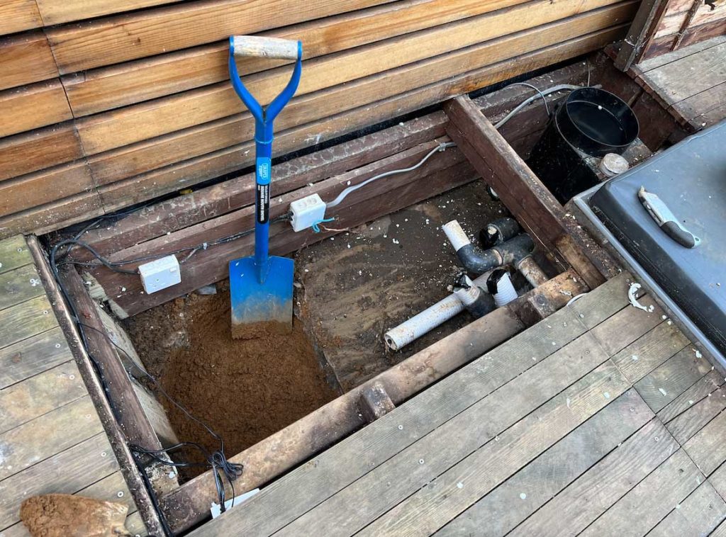
New Plumbing is starting to take shape
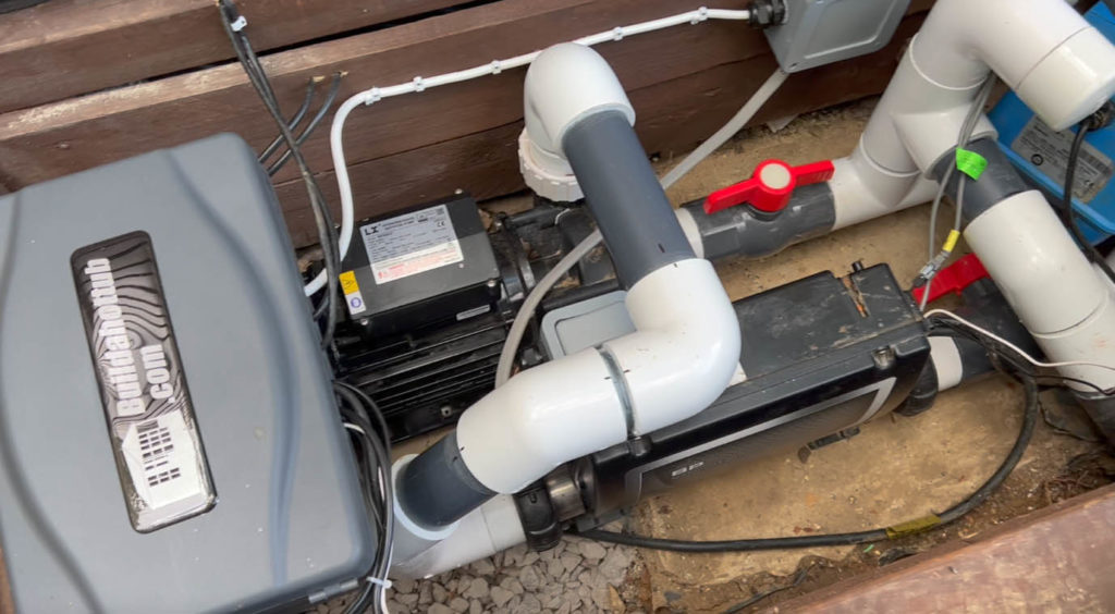
First things first, what a difference!! Already you can see that the joints are perfectly made. The angles are also perfect. Nothing has been “forced” to fit, they just fit.
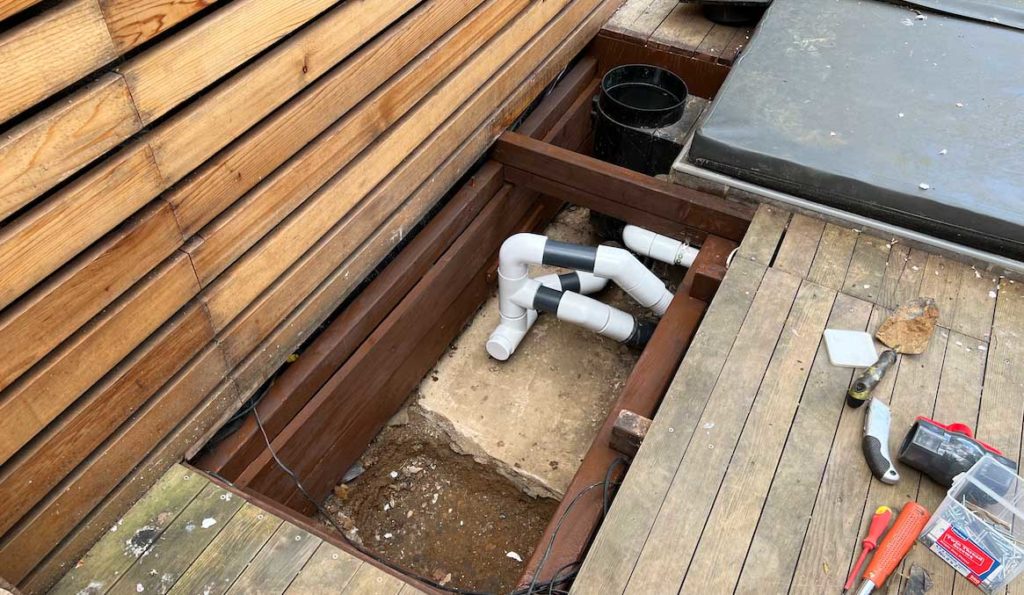
You can see here that my plumbing skills have certainly improved over the years. Especially when you take a look at the image above with all that epoxy – ouch! The new plumbing above I know will not leak. Why? Because the joints are made properly of course!
Yes, it took a bit of planning and careful measurements, but this is what you should be doing. Not ordering tubes and tubes of epoxy off Amazon to fix your leaks! (Yes, I’m guilty here)
In the picture above, you can see that I have the skimmer connected to the two lower drains which tee into the inward flow on the pump. There is a temporary stopper in there just to keep unwanted “guests” out of my plumbing.
I’m actually going to remodel the remodel as it was at this point that I decided that I would add an air source heat pump.
There will be a ball valve and then a pump union thread on the other end of this.
New Blower Position
Previously, the blower was just “shoved” in behind the skimmer. Yes, literally shoved in. What I decided that I would do was to build a small shelf over the inward plumbing and it would be housed there.
In that way, I could send the pipework up vertically and have it over the waterline too. This means that even with the check valve, there would be no water coming down the air lines into my blower.
This is good practice here not to just rely on the check valve to keep the water out. Take your blower lines up and over the waterline and there is no way water can ever enter your blower – gravity will not let it.
It also has de-cluttered things dramatically as previously; the air pipe was just at a funny angle wrapping around the skimmer – not ideal!
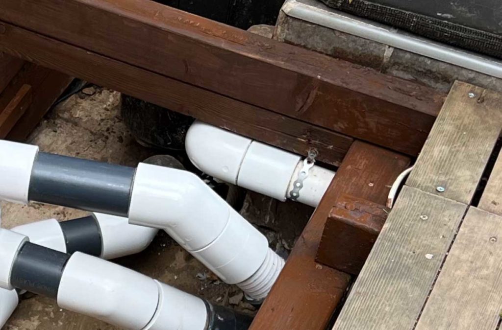
I’ve also supported the pipe with a supporting chain. Pipes should not just be left to hang; wherever possible they should be clipped in place and supported. In this way, they will not “wiggle lose” over time.
New retaining walls and a fresh coat of stain.
The next stage of the renovation was to put some new retaining walls is. I removed all the cables and will be re-doing that part next, and then fitted some new walls. They are just simple wood panels, more to keep the earth back than anything else.
I don’t intend to make the control room watertight as there would be nowhere for the water to go in the event of a leak. By having it somewhat open, water can drain into the ground. My worry initially was water coming up from the ground. However, quite a few years in that has never happened so I am just going to put stones on the base this time instead of a timber finish.
Support your Pipework
One of the things that I didn’t do previously was support my pipework. Pipes when full of water actually weigh a huge amount. This puts pressure on the joints so in order to avoid this, I have supported all my pipework this time around.
You can see here on the 1.5″ air lines that I have a metal clip holding them firmly in place.
Tidy Cables and a Waterproof Electrical Box
I really wanted to do things properly this time around in the control room so I have tidied up all the electrical cabling and also have everything electric wise plugged into an IP55 box. This is as opposed to a regular socket bolted to the sides as you can see on the original control room. Yes, it was pretty water tight and out of the elements, but I think I was taking a chance with a regular socket – not even an all weather one!
Now, everything fits nicely into the watertight box. Much tidier!
Remodel Complete!
And there we have it – a fully functional remodel of the control room complete! What a difference. It is now something that I am actually proud of! You will notice that there is now no filter. This is because I have moved the filter onto the heating circuit for the air source heat pump. This I will cover in much more detail in my next post.
Finally – a control room that I am proud of!
Can I Help You?
If I can help you in any way I would love to hear from you. You can get in touch using the form below.
Thanks - Andi
 Hi, Andi here. I own Buildahottub.com and also write all of the articles and info pages on the site. Some years back now, I built my own hot tub but struggled to find the information I needed. So, once my tub was complete, I started this website to help others in their own pursuit of hot tub and plunge pools DIY building information.
Fast forward to 2025, I've helped over 1400+ DIY customers just like you all over the world build hot tubs and pools. Have a good look around the site, there are lots of resources here. Please do get in touch if I can help you. - Cheers, Andi


